
stm32
准备工作
STM32是ST公司基于ARMCortex-M内核开发的32位微控制器
stm32F1的所有外设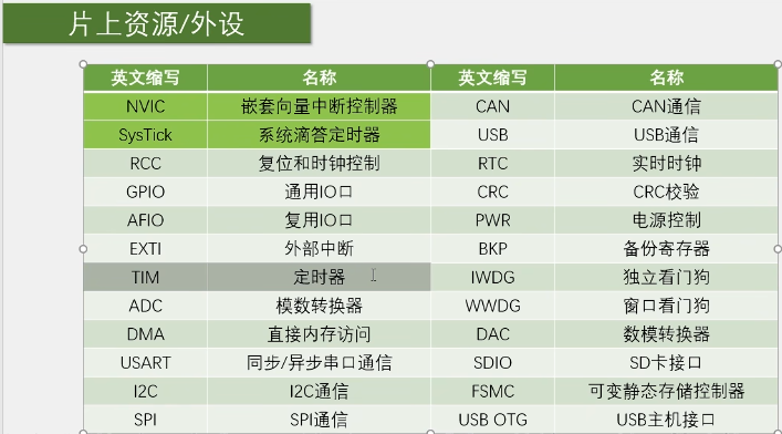
约定成俗的杜邦线:黑色接地(gnd),红色接vcc,黄或橙接时钟,蓝色或绿色接数据线,白色或灰色或紫色接控制线或其他线
GPIO输出
GPIO介绍
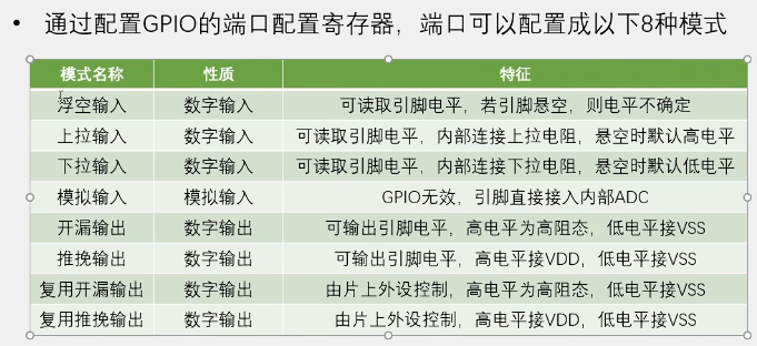
在STM32中I/O引脚,又称GPIO,可以被软件设置成各种不同的功能及模式。
分为输入(4 种)和输出 / 复用(4 种)两大类,核心区别是引脚是否主动输出电平、是否由外设复用;
GPIO相关寄存器配置
调用库函数来配置寄存器,可以脱离底层寄存器操作,使得开发效率提高,同时易于阅读和维护。GPIO相关的函数和定义分布在固件库文件stm32f10x_gpio.c和头文件stm32f10x_gpio.h中。
GPIO——IniTypeDef结构体的定义:1
2
3
4
5
6
7typedef struct
{
unit16_t GPIO_Pin; //GPIO引脚
GPIOMode_TypeDef GPIO_Mode; //GPIO模式
GPIOSpeed_TypeDef GPIO_speed; //GPIO速度
}
八个模式1
2
3
4
5
6
7
8
9
10
11typedef enum
{ GPIO_Mode_AIN = 0x0,//模拟输入模式
GPIO_Mode_IN_FLOATING = 0x04,//浮空输入模式
GPIO_Mode_IPD = 0x28,//下拉输入模式
GPIO_Mode_IPU = 0x48,//上拉输入模式
GPIO_Mode_Out_OD = 0x14,//开漏输出模式
GPIO_Mode_Out_PP = 0x10,//推挽输出模式
GPIO_Mode_AF_OD = 0x1C,//复用功能开漏输出
GPIO_Mode_AF_PP = 0x18//复用功能推挽输出
}GPIOMode_TypeDef;
OLED
串口调试:通过串口通信,将调试信息发送到电脑端,电脑使用串口助手显示调试信息
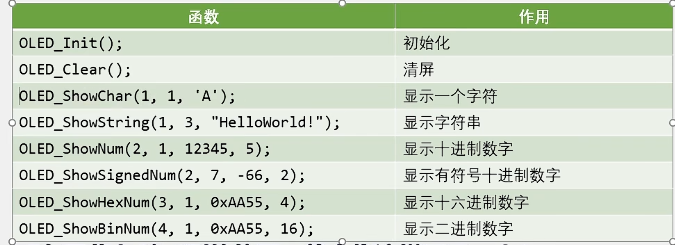
显示屏调试:直接将显示屏连接到单片机,将调试信息打印在显示屏上
Keli调试模式:借助Keli软件的调试模式,可使用单步运行,设置断点,查看寄存器及变量等功能
外部中断
中断:在主程序运行过程中,出现了特定的中断触发条件,使得cpu暂停当前正在运行的程序,转而去处理中断程序,处理完成后又返回原来被暂停的位置继续运行。
中断嵌套:当一个中断程序正在运行时,又有新的更高优先级的中断源申请中断,cpu再次暂停当前中断程序,转而去处理新的中断程序,处理完成后依次进行返回。
stm32中断:68个可屏蔽中断通道(就是中断源)。
NCIC的中断优先级由优先级寄存器的4位(0-15)决定,这4位可以进行切分,分为高n位的抢占优先级和低4-n位的响应优先级。
抢占优先级高的可以中断嵌套,响应优先级高使的可以优先排队,抢占优先级和响应优先级均相同的按中断号排队。
定时器
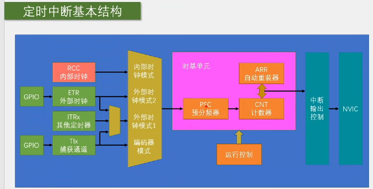
定时器可以对输入的时钟进行计数,并在计数值达到设定值时触发中断
不仅具备基本的定时中断功能,而且还包含内外时钟源选择、输入捕获、输出比较、编码器接口、主从触发模式等多种功能。
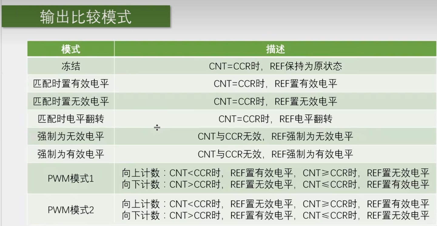
TIM输出比较
输出比较可以通过比较CNT与CCR寄存器值的关系,来对输出电平进行置1、置换0或翻转的操作,用于输出一定频率和占空比的PWM波形
PWM脉冲宽度调制
代码保存
点亮第一个led灯
1 |
|
led灯闪烁
1 |
|
led流水灯
1 |
|
蜂鸣器
1 |
|
按键控制led
1 |
|
独立按键控制led
1 |
|
光敏传感器连传感器
1 |
|
旋转传感器
1 |
|
PWM
定时中断
1 |
|
定时器外部时钟
1 |
|
呼吸灯闪烁
1 |
|
舵机驱动
1 |
|
电机驱动
1 |
|
输入捕获模式测频率
1 |
|
PWMI模式测频率占空比
1 |
|
测数
1 |
|
AD转换器
AD单通道
1 |
|
AD多通道
1 |
|
DMA存储器
DMA数据转运
1 |
|
DMA+AD通道
1 |
|